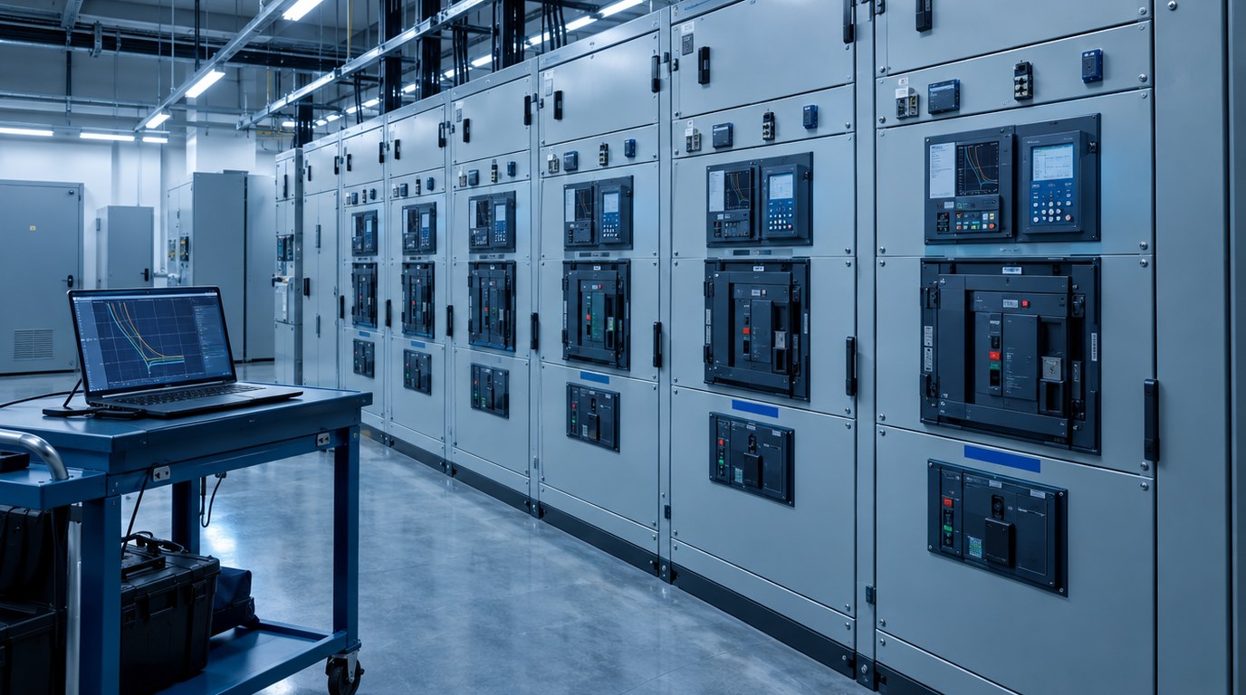
- A short circuit study finds the largest and smallest fault current at every bus, panel and protective device in the system.
- A coordination study selects device ratings and trip settings so the device nearest a fault opens first and the rest of the building stays energized.
- NEC 110.9, 110.10 and 110.24 tie equipment ratings and field markings to the calculated fault current.
- Emergency, standby, elevator and healthcare life safety circuits face selective coordination requirements.
- Run a preliminary calculation in design development, then a final study after equipment submittals.
- The same model feeds arc flash labels, so one data set supports three deliverables.
- What Are Short Circuit and Coordination Studies?
- How the Studies Work
- Types of Calculations and Protection Schemes
- Code and Standards Requirements
- Applications by Building Type
- Design Process and Deliverables
- Special Cases and Difficult Conditions
- How to Specify the Studies and What Drives Cost
- Best Practices, Common Mistakes and Maintenance
- Where Budlong Delivers This
- Related Reading
- Frequently Asked Questions
Every electrical system is designed for normal days, but its protective devices are chosen for the worst day the building will ever have. A bolted fault on a main switchboard can release tens of thousands of amperes in a few cycles, and whether the equipment survives it depends on decisions made months earlier on the drawing board. That is the work of short circuit and coordination studies, a core part of the electrical engineering services we provide to owners, architects and developers.
Budlong has been designing building systems since 1958, and the lesson from decades of project work is consistent: studies done late are expensive, and studies done early are cheap insurance. This guide explains what the studies calculate, the codes behind them, how they connect to the rest of a full MEP design, and when to schedule them so they protect the schedule instead of delaying it.
1. What Are Short Circuit and Coordination Studies?
The short circuit study
A short circuit study is a calculation of the current that would flow if a fault occurred at a given point in the system. It is performed for every bus, switchboard, panelboard and major device, and it produces two families of numbers. The maximum values, with every source connected and every motor running, check that equipment can interrupt or withstand the fault. The minimum values, with sources out of service, check that protective devices will still sense and clear a low-level fault in time.
The coordination study
A coordination study, often called a protective device coordination study, overlays the time-current curves of series devices on one chart and checks that they operate in the right order. When a branch breaker trips on a short circuit, the feeder breaker above it should stay closed, and so should the main. Coordination is how engineers keep a single failed light fixture or motor from darkening an entire floor.
Why they travel together
The two studies answer different questions with shared data. The short circuit study asks whether a device is strong enough. The coordination study asks whether it is set correctly. A breaker that is strong enough but poorly set can still trip an entire building, and a well-set breaker that is under-rated can fail violently. For that reason we treat them as one scope, and we extend the same model to the arc flash analysis discussed in our guide to arc flash analysis and NFPA 70E compliance.
Also Read: Arc Flash Analysis and NFPA 70E Compliance
2. How the Studies Work
Building the model
The engineer starts from the single-line diagram and converts it into a network model: utility source, transformers, cables, bus duct, generators, motors and protective devices. Each element carries an impedance. The software, commonly a commercial power system package such as ETAP, SKM PowerTools or EasyPower, reduces the network to an equivalent impedance at each bus and solves for fault current using methods recognized in IEEE 551, the Violet Book on short circuit calculations.
A worked sense of scale
Consider a 1,500 kVA transformer with a 480 volt secondary and 5.75 percent impedance. Its full load current is about 1,800 amperes. Dividing by the per-unit impedance gives a fault current of roughly 31,000 amperes at the secondary terminals if the utility is treated as an infinite source. Real results are somewhat lower because utility and cable impedance reduce the value, and somewhat higher at motor-heavy buses because running motors feed current back into the fault.
Sources of fault current
- Utility: the serving utility provides available fault current and X/R ratio at the point of connection, usually as maximum and minimum values.
- Transformers: impedance limits the current they can deliver, which is why transformer data from the submittal matters.
- Generators: contribute for several cycles at a level set by subtransient reactance.
- Motors: induction and synchronous motors act as short-lived sources, with induction motors commonly modeled at several times their full load current for the first cycles.
- Inverter-based sources: solar and storage contribute only a limited multiple of rated current, but they must be modeled.
From fault current to curves
Once fault values are known, the engineer plots each device on a time-current chart: the long-time pickup, the short-time pickup and delay, the instantaneous trip, and any ground fault element. Fuse curves, relay curves and transformer inrush and damage points are added. The task is to shape settings so that a downstream device clears first with a safe margin, while still protecting cable and transformer damage limits.
3. Types of Calculations and Protection Schemes
Short circuit calculation methods
Engineers choose among several approaches depending on the project. Hand methods such as the per-unit or ohmic method suit small systems and sanity checks. Point-to-point methods give quick conservative estimates for panel-level work. Full software models, with duty-specific calculations for first-cycle, interrupting and 30-cycle conditions, are the standard for any building with a main switchboard, generator or medium-voltage source.
Duty types
First-cycle values check bracing and closing capability. Interrupting-time values, often at one and a half to four cycles, check breakers and fuses. Thirty-cycle values apply to time-delayed devices and relays. A thorough report states which duty each result represents.
Coordination strategies
There are several ways to arrange protection, and each carries trade-offs in cost, continuity and arc energy.
| Approach | How it works | Best used for | Main trade-off |
|---|---|---|---|
| Fully selective coordination | Only the device immediately upstream of the fault opens, for any fault level up to the available current | Emergency systems, hospitals, elevators, data centers | May require larger frames, delay settings or zone interlocking |
| Partial coordination | Selective up to a stated fault current, then devices may open together | General commercial distribution where cost matters | Larger outages possible for severe faults |
| Fully rated | Every device is individually rated for the available fault current | New installations with moderate fault levels | Higher equipment cost at high fault levels |
| Series rated | Upstream device helps a downstream device interrupt, with tested combinations | Cost-sensitive branch circuits where permitted | Cannot be used where motor contribution is significant or for selectively coordinated systems |
| Current limiting | Fuses or limiters cut let-through energy before the peak | High fault current, small downstream equipment | Replacement stock and coordination with breakers |
Protection devices and their curves
Molded case and insulated case breakers with electronic trip units give the most adjustable curves. Power circuit breakers suit large service equipment. Fuses coordinate predictably when ratio rules are respected. Relays with ANSI device numbers 50 and 51 for phase overcurrent, 50G and 51G for ground, and 67 for directional overcurrent dominate medium-voltage systems.
4. Code and Standards Requirements
National Electrical Code provisions
The National Electrical Code, published by NFPA as NFPA 70, makes the studies an engineering necessity even where it never uses the word study. The sections that matter most:
- 110.9: equipment must have an interrupting rating at or above the current available at its line terminals.
- 110.10: protective devices, impedance and component short-circuit ratings must allow the system to clear a fault without extensive damage.
- 110.24: for service equipment in other than dwelling units, available fault current and the date of the calculation must be field marked, and the marking must be updated when modifications change the value.
- 240.86 and 240.87: series ratings and arc energy reduction for larger circuit breakers.
- 517.26, 620.62, 700.32, 701.32 and 708.54: selective coordination for healthcare essential systems, elevators, emergency systems, legally required standby systems and critical operations power systems.
California adoption
California enforces the California Electrical Code, Part 3 of Title 24, which adopts the NEC with state amendments. The code is published through the International Code Council and administered by the California Department of General Services building standards program. Always confirm the adopted edition and local amendments. Our primer on Title 24 and the California energy code explains how the parts fit together.
Referenced standards
The IEEE color book series underpins the engineering method: IEEE 551 for short circuit calculations, IEEE 242 for protection and coordination, and IEEE 399 for power system analysis. Device ratings follow product standards from UL, including UL 489 for molded case breakers, and from ANSI and IEEE for power breakers.
Selective coordination is a code requirement for life safety and emergency systems. Elsewhere it is a design choice, and the owner should make that choice knowingly.
Also Read: Electrical Engineering for Safety, Reliability and Efficiency
5. Applications by Building Type
Office, retail and mixed-use
Commercial buildings typically have a utility service, a main switchboard, several distribution panels and many tenant panels. The main risk is under-rated tenant equipment on a strong service, and the study confirms where series ratings are acceptable. Our commercial electrical services team runs the preliminary calculation before tenant improvement drawings are issued.
Healthcare
Hospitals have the strictest coordination needs because the life safety, critical and equipment branches must keep operating through downstream faults. Projects such as Cedars-Sinai Medical Center show how many levels of distribution can sit between the utility and a patient room. See our health facilities experience for more.
Mission critical and data centers
Uptime depends on fault isolation. Data center designs use multiple sources, static transfer devices and fast-acting protection, and the studies must cover every operating configuration. Our work in mission critical facilities and the article on power distribution for data centers describe the architecture.
Aviation, transit and laboratories
Airports combine very large services, generators and sensitive baggage and terminal loads. Laboratories and industrial plants add large motors and process equipment. Both are covered by our aviation and industrial and laboratory practices.
| Building type | Typical fault current drivers | Coordination priority |
|---|---|---|
| Office and retail | Utility strength, large transformers, tenant panels | Interrupting ratings at tenant panels |
| Hospital | Multiple transformers, generators, large motor loads | Selective coordination of essential branches |
| Data center | Parallel sources, UPS, high-capacity busway | Isolation across every operating mode |
| Airport and transit | Medium-voltage distribution, generators, large chargers | Source transfer and relay settings |
| Laboratory and industrial | Large motors, VFDs, process equipment | Motor contribution and starting current |
Need a short circuit and coordination study?
Our electrical engineers can scope the right level of study for your project, from a preliminary calculation to a full selective coordination report.
Talk to a Budlong electrical engineer
6. Design Process and Deliverables
Stage by stage workflow
The studies belong in several project phases, not one. Early estimates guide equipment choices, and final data closes the loop before energization.
| Project stage | Study activity | Output |
|---|---|---|
| Schematic design | Request utility fault current, estimate transformer sizes | Preliminary service rating and space needs |
| Design development | Preliminary short circuit model | Interrupting rating schedule for drawings |
| Construction documents | Specify study scope and equipment requirements | Specification section and device schedules |
| Submittals | Final short circuit and coordination study | Report, curves and recommended settings |
| Startup and commissioning | Verify installed settings against the report | Settings records and field markings |
What the report should contain
- One-line diagram with bus names matching the drawings and equipment labels.
- Input data tables, with assumptions and missing data clearly flagged.
- Short circuit results for each bus, with the duty type identified.
- Equipment evaluation comparing available fault current with each interrupting or withstand rating.
- Time-current curve plots grouped by logical coordination paths.
- A recommended settings table for every adjustable device.
- A list of deficiencies and the proposed fixes.
Coordination with other disciplines
Early coordination keeps results from surprising the team. Space for larger switchgear, changes to the one-line, and generator sizing all flow from the studies. Our article on early MEP coordination explains how early data prevents rework, and the guide to BIM coordination and clash detection shows how equipment dimensions get locked in.
Also Read: Electrical Load Calculation for Commercial Buildings
7. Special Cases and Difficult Conditions
Generators and cogeneration
On-site generation changes the fault picture twice. A generator adds fault current when it is running, and its lower fault current relative to the utility can make fault clearing slower. Emergency generator replacement jobs, such as the City of Anaheim emergency generators project, rely on updated studies to confirm that existing breakers still interrupt and coordinate with the new source. Cogeneration plants like the San Antonio Community Hospital cogen plant add parallel operation with the utility, which adds modes to study.
Solar, storage and other inverter sources
Inverter sources limit their output current, so they rarely raise interrupting duty, but they can reduce the current seen by upstream devices and affect sensitivity. Models must include them and test minimum fault cases.
Existing buildings and utility changes
Utility upgrades quietly raise available fault current. A building that was safe in 1995 may have under-rated panels today. Any change to a service transformer, a nearby utility feeder, or a new on-site source should trigger a review. Our guide on planning for future load expansion outlines how to leave headroom.
High resistance grounding and ground faults
Resistance grounded systems limit ground fault current to a few amperes and allow continued operation through a first ground fault. Their coordination study centers on ground fault detection and alarms, not on tripping, but line-to-line fault coordination still applies.
8. How to Specify the Studies and What Drives Cost
What to write in the specification
A good specification section names the standards used, the software capability, the required deliverables, the timing of the study relative to submittals, and who pays for settings adjustments. It should also require the contractor to supply equipment data, and require the final study to be accepted before energization. Review our CD package guidance for how this fits the drawing set.
Who should perform the study
Studies can be performed by the design engineer of record, the equipment manufacturer, or an independent testing firm. Each option has trade-offs in independence and speed. For coordinated life safety systems, the engineer of record is best placed to understand the intent of the design, while manufacturers are best placed to supply accurate trip unit data.
Cost drivers
| Cost driver | Why it matters | How to control it |
|---|---|---|
| Number of buses and devices | More nodes mean more data entry and review | Define scope by system level up front |
| Data quality | Missing nameplates trigger field survey time | Provide as-builts and equipment lists early |
| Generators and motors | Extra sources and operating modes multiply cases | List operating modes in the scope |
| Selective coordination goals | May need iterations and equipment changes | Identify required systems early |
| New versus existing | Existing buildings need field verification | Budget a survey phase |
For a broader view of budgeting, see our article on how to estimate MEP engineering costs.
9. Best Practices, Common Mistakes and Maintenance
Best practices
- Request utility fault current data in schematic design, and confirm both maximum and minimum values.
- Specify a coordination goal for each system, and state it in the drawings.
- Require the final study to use approved submittal data, not catalog assumptions.
- Keep the model as a living file, and hand it over to the owner at closeout.
Common mistakes
- Assuming an infinite utility source and overestimating or underestimating results.
- Ignoring motor contribution on large mechanical or process buses.
- Setting instantaneous pickups so high that coordination looks perfect but arc energy is not controlled.
- Completing the study after equipment has shipped, leaving little room to fix problems.
- Leaving field markings out of date after a utility or equipment change.
Testing and maintenance
Settings on paper are not settings in the field. Testing and commissioning confirm that trip units are set as recommended, that ground fault functions work, and that relays operate as designed. Our building commissioning process includes a check of protective settings, and our commissioning services can verify them independently. Failures in power systems usually trace back to unverified settings, as discussed in why data center power systems fail.
Also Read: The Building Commissioning Process
- Short circuit studies check strength. Coordination studies check selectivity.
- NEC 110.9, 110.10 and 110.24 make fault current a design input, not an afterthought.
- Selective coordination is mandatory for specific life safety and emergency systems.
- Run a preliminary study early and a final study after submittals.
- Update the studies after any change to the source, the transformers or the protection.
- Verify settings in the field during commissioning.
10. Where Budlong Delivers This
Budlong staffs offices in Glendale, downtown Los Angeles, Camarillo and Fremont, and serves Los Angeles, Ventura, Orange, San Bernardino, Riverside and Santa Barbara counties. Our teams pair local utility knowledge with a portfolio that includes LAX bus charging and hospital cogeneration plants. Explore our MEP portfolio for more examples.
11. Related Reading
12. Frequently Asked Questions
What is the difference between a short circuit study and a coordination study?
A short circuit study calculates the maximum and minimum fault current available at each point in the electrical system, which tells you whether equipment can safely interrupt or withstand a fault. A coordination study uses those values to select and set protective devices so that only the device closest to a fault opens. The first study sets the ratings, and the second sets the trip settings.
Does every project need both studies?
Any project that adds or changes service equipment, switchboards, panelboards, transformers or generators needs at least a short circuit evaluation to confirm interrupting ratings. A coordination study is required where the NEC calls for selective coordination, such as emergency systems, healthcare essential systems and elevators, and it is sound practice for any building with several levels of distribution. Very small tenant work may be covered by a short documented calculation.
When should the studies be done in the project schedule?
Run a preliminary short circuit calculation during schematic or design development so equipment ratings can be written into the drawings and specifications. Run the final short circuit and coordination study after approved equipment submittals, because actual transformer impedances and breaker trip units change the results. The final study must be complete before energization and before labels are applied.
What does the NEC say about interrupting ratings?
NEC 110.9 requires equipment intended to interrupt current at fault levels to have an interrupting rating at least equal to the current available at its line terminals. NEC 110.10 requires protective devices, impedance and component ratings to be selected so the system can clear a fault without extensive damage. The adopted edition and local amendments govern the exact text on your project.
What information does the engineer need to run the studies?
The engineer needs the utility available fault current and X/R ratio, transformer sizes and impedances, conductor sizes, types and lengths, generator and motor data, and the make, model and settings of every protective device. For existing buildings, a field survey fills the gaps. Missing or assumed data should be flagged in the report so the owner knows which results are firm.
Is selective coordination always required?
No. The NEC requires selective coordination for specific systems, including emergency systems, legally required standby systems, critical operations power systems, elevator circuits and healthcare life safety circuits. For ordinary loads, coordination is a design goal that balances continuity of service against cost and arc energy, and partial coordination is often accepted by the owner.
How often should the studies be updated?
Update them whenever the utility source, a transformer, a generator, a large motor load, a protective device or the system configuration changes. The NEC also expects field markings to be updated when modifications change the available fault current. Many owners also review the studies on the same cycle as their arc flash risk assessment, which NFPA 70E expects at intervals not exceeding five years.
How does a short circuit study relate to an arc flash study?
The arc flash study starts from the same fault current values and the same protective device curves, then adds enclosure, gap and working distance inputs to estimate incident energy. A reliable short circuit and coordination model is therefore the foundation for accurate arc flash labels, and doing the three studies together avoids duplicated data collection.
What drives the cost of the studies?
The main drivers are the number of buses and protective devices modeled, the quality of the available data, the presence of generators, motors or inverter based sources, whether the building is new or existing, and how many design iterations are needed to reach selective coordination. Field data collection in an existing building is often the largest variable.