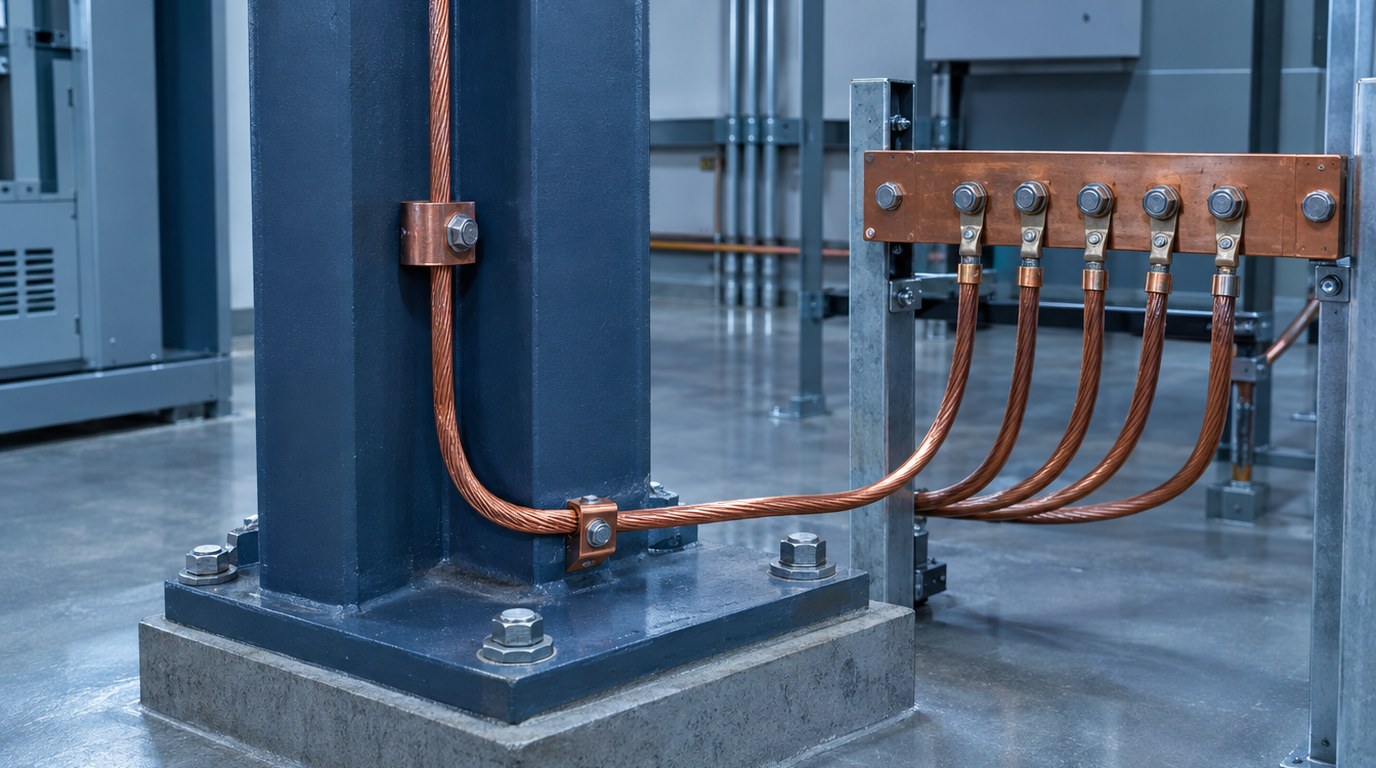
- Grounding ties the system to earth. Bonding ties metal parts to each other and to the source.
- Fault current returns through bonded metal and conductors, never through the earth.
- The neutral is bonded to ground once, at the service or at a separately derived source.
- Every electrode present at a building is joined into one grounding electrode system.
- Table 250.66 and Table 250.122 drive conductor sizes for electrodes and equipment.
- Commissioning tests prove the design before the building is energized and occupied.
- What Is Grounding and Bonding Design?
- How a Grounded Electrical System Works
- System Grounding Types and Electrode Options
- NEC Article 250 and California Requirements
- Grounding Needs by Building Type
- Design Process and Deliverables
- Special Cases and Niche Conditions
- How to Specify the System and What Drives Cost
- Best Practices, Mistakes and Testing
- Where Budlong Delivers This
- Related Reading
- Frequently Asked Questions
A fault in a commercial building should clear in a fraction of a second, not smolder inside a conduit run. Grounding and bonding design is what makes that happen. This guide walks through how NEC Article 250 shapes service grounding, equipment bonding, electrode selection and field testing, and how engineers carry those decisions from the one-line diagram to the finished building. Budlong delivers this scope through its electrical engineering services and commercial electrical services groups, as part of coordinated MEP engineering services.
The audience here is owners, architects, developers and facility managers who need to understand what is being specified and why. The firm behind the advice has worked in Southern and Northern California since 1958, and you can read more about that history in our story. The sections below move from first principles to code requirements, building-specific needs, special cases and testing.
1. What Is Grounding and Bonding Design?
Grounding and bonding design is the engineering of every intentional connection between the electrical system, the building’s metal parts and the earth. It produces a drawing set, a specification and a testing plan that together define where conductors connect, how large they are, and what they must achieve under fault conditions.
Grounding versus bonding
The two terms are often used as if they meant the same thing. They do not. Grounding is a connection to the earth, made through electrodes such as concrete-encased rebar, ground rings and rods. Bonding is a connection between metal parts, made through jumpers, conductors and listed fittings. A building needs both to be safe.
What NEC 250.4 says the system must do
Section 250.4 states the performance goals in plain language. Grounding limits voltage from lightning, line surges and unintentional contact with higher voltage lines. It stabilizes voltage to earth during normal operation. Bonding provides a low impedance path so overcurrent devices open quickly. Finally, bonding reduces touch voltage between metal surfaces a person might contact at the same time.
Earth is not the fault return path. The soil is far too resistive to trip a breaker. The return path is the bonded metal and conductors that lead back to the source, which is why bonding quality matters more than electrode resistance for protection against shock and fire.
Also Read: Arc Flash Analysis and NFPA 70E Compliance
2. How a Grounded Electrical System Works
Think of the grounding system as three cooperating networks: the equipment grounding network, the neutral and system bonding point, and the grounding electrode system. Each does a different job, and design errors usually come from mixing them up.
The effective ground-fault current path
When a phase conductor touches a metal enclosure, current must flow back to the source through a path of very low impedance. In a typical 480Y/277 volt system it travels along the equipment grounding conductor or metal raceway, reaches the service bonding point, crosses the main bonding jumper to the grounded conductor, and returns to the transformer winding. The result is a high current that opens the breaker or fuse in a few cycles. Section 250.4(A)(5) requires this path to be permanent, continuous and low impedance.
Why the neutral bond happens once
The grounded conductor is connected to the equipment ground at one place, the service or the source of a separately derived system. Adding a second bond downstream gives neutral current a parallel route through conduit, trays and structural steel. That creates objectionable current under 250.6, causes nuisance trips of ground-fault protection and can inject noise into sensitive electronics. Field inspections of older buildings frequently find this problem in subpanels and disconnects that were wired with a neutral bar bonded to the enclosure.
The grounding electrode system
The electrode system gives the building a stable reference to earth and a place to discharge lightning and surge energy. It does not carry fault current for protective devices to see. Under 250.50, all electrodes present at the building are bonded into a single system, so rebar, water pipe, rods and rings share one potential. The grounding electrode conductor, sized from Table 250.66, links that system to the service.
Where a design depends on accurate fault duties, grounding decisions connect directly to construction document packages for electrical systems, because the one-line, the panel schedules and the grounding details must agree.
3. System Grounding Types and Electrode Options
Two decisions define the system. The first is how the source is grounded. The second is which electrodes connect that system to earth.
Choosing how the source is grounded
| System type | Typical use | Behavior on first ground fault | Trade-off |
|---|---|---|---|
| Solidly grounded | Most commercial 208Y/120 and 480Y/277 volt systems | High fault current, breaker opens quickly | Highest arc flash energy at the fault, simplest to protect |
| High-resistance grounded | Continuous processes, some mission critical and industrial loads | Fault current limited to a few amperes, alarm sounds | Needs trained staff to locate and clear the first fault |
| Low-resistance grounded | Medium voltage distribution, campuses, large motors | Current limited to a set value, relay trips | Requires relay coordination and resistor maintenance |
| Ungrounded or isolated | Specialty cases such as isolated power in critical care rooms | Monitored with a line isolation monitor | Second fault is dangerous, so monitoring is essential |
Choosing electrodes
Section 250.52 lists the electrodes the Code recognizes. A project may have several at once, and all must be bonded together. Their practical value differs a great deal.
| Electrode | Key requirement | Design comment |
|---|---|---|
| Concrete-encased electrode | At least 20 ft of 1/2 in rebar or 4 AWG bare copper, in at least 2 in of concrete near the footing bottom | Excellent in new construction, coordinate with structural drawings early |
| Ground ring | At least 20 ft of bare copper, 2 AWG or larger, buried at least 30 in | Common around data rooms, utility yards and generator pads |
| Rod, pipe or plate | Supplement with a second electrode unless resistance is 25 ohms or less | Flexible fix for retrofits and remote equipment |
| Metal underground water pipe | At least 10 ft in contact with earth, must be supplemented | Never the only electrode, plastic pipe sections remove it entirely |
| Building steel | Allowed where effectively grounded and bonded | Useful for large frames, verify continuity at splices |
High-density and resilient facilities add engineered grids beyond these basics. The design logic in power distribution for data centers shows how grounding scales with redundancy, and the mission critical practice applies the same discipline to other uptime-sensitive environments.
4. NEC Article 250 and California Requirements
NFPA 70, the National Electrical Code, is published by NFPA. California adopts it, with amendments, as the California Electrical Code within the California Building Standards Code. The Building Standards Commission, part of the Department of General Services, publishes the state code set, and the International Code Council publishes the model codes that sit alongside it. Always confirm the adopted edition and local amendments before finalizing details.
The parts of Article 250 that drive design
- 250.24 and 250.28: service grounding, the grounded conductor and the main bonding jumper.
- 250.30 and 250.35: separately derived systems, including transformers and generators.
- 250.50 to 250.68: electrodes, the electrode conductor and connection methods.
- 250.92 to 250.106: bonding of services, metal piping, structural steel and lightning protection.
- 250.118 to 250.126: equipment grounding conductor types, sizing and identification.
Conductor sizing at a glance
The grounding electrode conductor is sized from the largest service conductor using Table 250.66. For example, a copper service conductor from 2/0 to 3/0 AWG typically calls for a 4 AWG copper electrode conductor, and one above 3/0 through 350 kcmil typically calls for 2 AWG. When the connection runs only to a rod, 250.66(A) caps the required size at 6 AWG copper, and for a concrete-encased electrode 250.66(B) caps it at 4 AWG copper. Equipment grounding conductors come from Table 250.122 and scale with the overcurrent device rating.
| Overcurrent device rating | Minimum copper equipment grounding conductor |
|---|---|
| 20 A | 12 AWG |
| 60 A | 10 AWG |
| 100 A | 8 AWG |
| 200 A | 6 AWG |
| 400 A | 3 AWG |
| 800 A | 1/0 AWG |
Ground-fault protection is a separate requirement. Section 230.95 calls for it on solidly grounded wye services over 150 volts to ground and up to 1000 volts phase to phase when the disconnect is rated 1000 amperes or more, and Section 517.17 adds a second level for hospitals.
Higher-voltage work, safety during energized maintenance and workplace rules fall under related documents. The Occupational Safety and Health Administration sets electrical safety expectations for workers, and IEEE publishes the engineering guides, including the Green Book for grounding practice and the standard for earth resistivity and ground resistance measurement.
Schools and hospitals in California
Public school work is reviewed by the Division of the State Architect, as described in the DSA process guide. Hospitals fall under HCAI, covered in the OSHPD and HCAI guide. In both cases, the plan reviewer will look for grounding details that match the adopted code edition.
5. Grounding Needs by Building Type
The same Article 250 text applies everywhere, but the engineering emphasis shifts with use.
Offices, retail and hospitality
Conventional solidly grounded systems dominate. The focus is a clean service entrance, correctly bonded metal water and gas piping, and a ground bar in each electrical room tied to building steel. Tenant improvements often fail here, because new subpanels are added without confirming the existing bonding.
Healthcare
Patient care areas add redundant grounding under 517.13, which pairs a metal raceway with an insulated copper conductor on branch circuits serving those spaces. Operating rooms and critical care spaces may also use isolated power. Teams working in health facilities pair grounding design with essential electrical system layout, as discussed in healthcare MEP design.
Airports and transit
Large metal structures, jet bridges, fuel systems and charging equipment make equipotential bonding a priority. Budlong’s aviation portfolio includes the LAX baggage screening facility, where conveyor and screening equipment depend on dependable bonding and clean power.
Schools, laboratories and data rooms
Campuses use distribution across many buildings, so each building needs its own electrode system and a clear bonding strategy for feeders. Laboratories mix metal piping, fume hoods and sensitive instruments, which is where industrial laboratories experience becomes valuable. Telecommunications spaces follow the TIA-607 family from TIA, which defines the backbone bonding conductor and ground busbars for communications rooms. For related cabling guidance, see low voltage design best practices.
Also Read: Electrical Engineering for Safety, Reliability and Efficiency
Need a grounding review before permit?
Our electrical engineers can check electrode design, bonding details and fault path logic against the adopted code edition before plans reach the reviewer.
Talk to an electrical engineer
6. Design Process and Deliverables
A reliable grounding design follows the same arc as the rest of the electrical package, but it has a few unusual dependencies, especially with the structural and civil teams.
From basis of design to details
- Basis of design: confirm the system voltage, source arrangement, resilience goals and any owner standards for resistance values.
- Site data: request soil resistivity data and the geotechnical report, and note rock, fill or seasonal moisture swings.
- Fault study: establish available fault current so conductor and bonding jumper ratings are sound.
- Grounding plan: locate the electrode system, ground bars, intersystem bonding termination and building steel connections.
- Details and specifications: show connection methods such as exothermic welds or listed compression lugs and state testing requirements.
- Submittal review and field observation: check shop drawings, inspect electrodes before concrete is placed and witness tests.
What the owner receives
Deliverables typically include a grounding plan at the foundation level, riser diagram notes, ground bar and bonding details, a testing specification section, and a record set after construction. Where the project runs on BIM, grounding conductors in cable tray and ground rings in the slab are modeled so conflicts with rebar and post-tension tendons surface early. Read more in MEP BIM coordination and clash detection.
Commissioning checkpoints
Testing is part of design, not an afterthought. A commissioning agent can verify bonding continuity, torque marks and electrode resistance before energization, and again before occupancy. Learn how that works in commissioning services.
7. Special Cases and Niche Conditions
Separately derived systems
Transformers and some generators create a new grounded source. Section 250.30 calls for a system bonding jumper at the source, a grounding electrode conductor to the nearest effective electrode, and supply-side bonding conductors sized to the Code. Skipping any one of these produces a floating neutral or a duplicate bond.
Emergency and standby generators
Whether a generator is separately derived depends on the transfer switch. A switch that opens the neutral makes the generator a separately derived source. A three-pole switch keeps the neutral solid and ties the generator to the service bond. Mistakes here cause ground-fault trips on transfer, a leading source of failed acceptance tests. Budlong’s generator work includes the USC NTT generator replacement, a useful example of how standby power affects grounding choices.
Solar PV and electrification
Photovoltaic arrays add DC grounding, array frame bonding and inverter-specific requirements under Article 690, with the electrode connection in 250.166. See photovoltaic design for how these systems are engineered. Charging infrastructure brings similar concerns, and the LAX bus charging station shows grounding scaled to heavy charging equipment.
Lightning protection and poor soil
Lightning protection systems follow NFPA 780 and must be bonded to the building grounding system under 250.106. In hillside or rocky sites, soil resistivity can make rods ineffective. Designers then lean on concrete-encased electrodes, deeper driven rods, chemical electrodes or ground enhancement material, and they document the reasoning rather than relying on a single rule of thumb.
Isolated ground and sensitive electronics
Isolated ground receptacles are permitted under 250.146(D), but they do not remove the need for an equipment grounding conductor sized and routed to the Code. Designers should reserve them for loads with a demonstrated need and avoid mixing them with ordinary receptacles on the same circuit.
8. How to Specify the System and What Drives Cost
Specifications should state the performance expected and the method to achieve it, because contractors price what is written. A section that only says “ground per code” invites substitutions that may technically pass inspection but fail an owner’s reliability goals.
What a good specification states
- Which electrodes are required and who is responsible for coordinating with the structural contractor.
- Connection method for each location, such as exothermic weld below grade and listed compression connectors above grade.
- Conductor type, color and marking for equipment grounding conductors and bonding jumpers.
- Testing requirements, the test method, the pass criteria and who witnesses them.
- Record documentation, including as-built photographs of buried connections before backfill.
Cost drivers
| Cost driver | What influences it | How to manage it |
|---|---|---|
| Electrode system | Soil resistivity, site access, depth to rock | Use footing rebar where possible and gather soil data early |
| Copper conductors | Service size, run length, number of ground bars | Place electrical rooms to shorten bonding runs |
| Connections | Exothermic welds, labor and inspection hold points | Standardize details and limit unique connection types |
| Testing | Number of electrodes, witness requirements | Combine with commissioning to reduce mobilizations |
| Remediation | Late discovery of poor soil or missed bonds | Review the design and inspect before concrete and backfill |
Grounding is a small share of electrical cost, but errors discovered after slab pours or energization are expensive to repair. Early planning pays for itself, as outlined in how to estimate MEP engineering costs.
9. Best Practices, Mistakes and Testing
Practices that work
- Bond all electrodes together and verify the connections are accessible for inspection.
- Run a wire-type equipment grounding conductor in every feeder and branch circuit, even where conduit would qualify.
- Keep ground bars in electrical rooms short, labeled and tied to building steel.
- Provide the intersystem bonding termination at the service for communications and cable television.
- Specify listed connectors for the environment, including corrosion resistance at rooftop and underground locations.
Common mistakes
- A second neutral to ground bond in a downstream panel or disconnect.
- Reliance on a single water pipe electrode when plastic pipe interrupts it.
- Undersized bonding jumpers for generators and transformers.
- Painted surfaces and anodized finishes under lugs, which spoil the connection.
- Rebar electrodes planned on the drawings but missed by the concrete crew.
Testing and maintenance
Ground resistance is commonly measured with the fall-of-potential method, described in IEEE guidance, or with a clamp-on tester where parallel paths exist. Continuity tests with a low-resistance ohmmeter confirm bonding. Torque verification and infrared scans catch loose lugs before they fail. Pair the first round of tests with the building commissioning process and repeat on a schedule appropriate for the facility.
A grounding system that passed a single resistance reading on opening day is not proof of long-term performance. Corrosion, construction damage and added equipment change the system. Build periodic verification into the owner’s maintenance program.
Also Read: Power Distribution System Design for Data Centers
- Bonding protects people and equipment during faults. Grounding stabilizes the system and handles surges.
- Bond the neutral once, and join every electrode into one system.
- Choose Table 250.66 and Table 250.122 sizes, then verify them against the fault study.
- Coordinate with structure early so concrete-encased electrodes are actually installed.
- Test at commissioning and on a schedule, and keep records.
10. Where Budlong Delivers This
Budlong supports clients through offices in Glendale, Downtown Los Angeles, Camarillo and Fremont, serving Los Angeles, Ventura, Orange, San Bernardino, Riverside and Santa Barbara counties. The local pages below describe the electrical and MEP resources available in each area.
11. Related Reading
12. Frequently Asked Questions
What is the difference between grounding and bonding?
Grounding connects an electrical system or equipment to the earth to stabilize voltage and manage surges. Bonding joins metal parts together so they stay at the same potential and so a fault has a low impedance path back to the source. Grounding talks to the earth. Bonding makes the building behave as one conductive body.
Does NEC 250 require a specific ground resistance value?
For a single rod, pipe or plate electrode, the NEC expects a resistance to ground of 25 ohms or less, otherwise a second electrode must be added. The Code does not set a universal target for the whole system. Designers often specify a lower value for data, healthcare and mission critical loads based on the owner’s performance goals.
Where should the neutral and ground be bonded?
At the service disconnect or at the source of a separately derived system, and nowhere downstream. A second neutral to ground bond on the load side creates a parallel path that sends normal neutral current onto conduit, enclosures and structural steel.
How is an equipment grounding conductor sized?
Table 250.122 sizes the equipment grounding conductor from the rating of the overcurrent device ahead of the circuit, for example 12 AWG copper for a 20 ampere device and 6 AWG copper for a 200 ampere device. The conductor is increased in proportion when circuit conductors are enlarged for voltage drop.
What is a concrete-encased electrode and why does it matter?
It is a length of at least 20 feet of steel reinforcing bar or bare copper conductor embedded near the bottom of a concrete foundation that is in direct contact with the earth. Concrete holds moisture and gives a large contact area, so it is among the most dependable electrodes in new construction. It must be planned with the structural team before the footings are poured.
Do generators need a neutral to ground bond?
It depends on the transfer scheme. A generator that is treated as a separately derived system gets its own system bonding jumper and grounding electrode connection, and the transfer switch must switch the neutral. A generator that is not separately derived relies on the bond at the service and the transfer switch does not switch the neutral.
How often should grounding systems be tested?
Test at commissioning, then on a schedule set by the owner and the risk of the facility. Many owners verify connections and electrode resistance annually or after major construction, lightning events or soil changes, and add infrared and torque checks to routine electrical maintenance.
What code applies to grounding in California commercial buildings?
California adopts the California Electrical Code, which is built on NFPA 70 with state amendments, as part of the California Building Standards Code. Hospitals also answer to HCAI review and schools to the Division of the State Architect. Always confirm the adopted edition and local amendments for the project.
Can conduit serve as the equipment grounding conductor?
Yes. Listed rigid metal conduit, intermediate metal conduit and electrical metallic tubing are permitted equipment grounding conductors when fittings are tight and the run is continuous. Flexible metal conduit is limited in length and by circuit rating. Many designers still specify a wire type conductor in every raceway for vibration, sensitive loads and healthcare spaces.