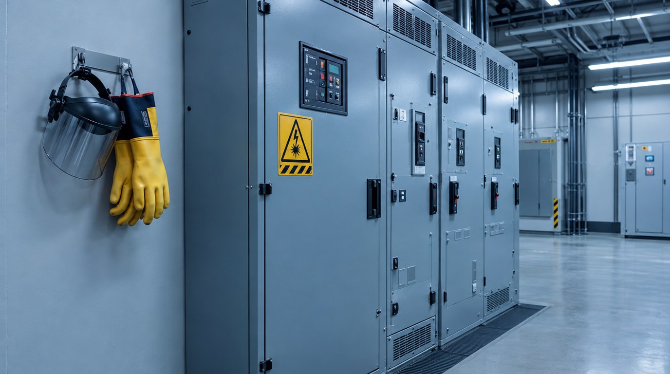
- An arc flash study converts fault current and protective device speed into incident energy, boundaries and PPE guidance for each piece of equipment.
- IEEE 1584-2018 is the calculation standard most studies follow, and it depends on electrode configuration, enclosure size, gap and working distance.
- Arcing time is the lever with the most influence, and it is set by protective device settings.
- NFPA 70E dictates label content and expects the risk assessment to be reviewed at least every five years.
- Mitigation ranges from maintenance mode switches to arc resistant switchgear, and each choice affects coordination.
- Timing matters: preliminary review in design development, final study after submittals, labels before energization.
- What Is an Arc Flash Study?
- How the Calculation Works
- Calculation Methods and Label Approaches
- Regulatory and Standards Requirements
- Applications by Building Type
- Design Process, Labels and Project Timing
- Special Cases and Difficult Conditions
- Specifying the Study and Understanding Cost
- Best Practices, Mistakes and Maintenance
- Where Budlong Delivers This
- Related Reading
- Frequently Asked Questions
An arc flash is a release of energy so intense that it can vaporize copper, throw molten metal and cause severe burns at a distance of several feet. Whether a worker standing at a switchboard faces a manageable event or a life-threatening one depends on numbers that can be calculated long before anyone opens a door. That calculation is the arc flash study, and it is one of the most practical deliverables in the electrical engineering services a project can buy.
Budlong has engineered power systems since 1958, and our history includes hospitals, laboratories, airports and generating plants where electrical work cannot always wait for a shutdown. This article takes a methodology-first view: the inputs, the math at a conceptual level, the label, the mitigation toolbox and the project stages where timing decides cost. For a compliance overview, start with our earlier guide below.
Also Read: Arc Flash Analysis and NFPA 70E Compliance
1. What Is an Arc Flash Study?
The hazard in engineering terms
An arcing fault occurs when current jumps through air between conductors or from a conductor to ground, often because of a dropped tool, a failed insulator, contamination or a loose termination. The arc converts electrical energy into heat, light, pressure and sound. The engineering question is how much thermal energy reaches a worker at a defined distance, and for how long.
What the study delivers
The study produces a table of results for every piece of equipment that may be examined or serviced while energized. Each row contains a bolted fault current, an arcing current, an arcing time, an incident energy value, an arc flash boundary and a recommended PPE level. The study also supplies labels, a summary of locations that exceed a chosen threshold and a list of mitigation options.
How it differs from related studies
| Study | Question it answers | Primary output |
|---|---|---|
| Short circuit study | How much current can flow in a fault? | Fault current at each bus |
| Protective device coordination | Which device opens first, and how fast? | Trip settings and curves |
| Arc flash study | How much thermal energy reaches a worker? | Incident energy, boundaries, labels |
| Electrical safety program | How does the owner manage work on live equipment? | Procedures, training, PPE policy |
An arc flash study does not make equipment safe by itself. It tells you how dangerous each location is, so that you can decide whether to reduce the hazard, restrict the work or protect the worker.
2. How the Calculation Works
The IEEE 1584-2018 approach
The IEEE 1584 guide gives empirical models built on large-scale laboratory testing. The 2018 edition calculates arcing current first, then incident energy, then the arc flash boundary. It covers three-phase systems from low voltage up to 15 kV within stated ranges of fault current, gap and enclosure size, and it uses a set of electrode configurations to represent how conductors are arranged inside the equipment.
Inputs that matter
- Voltage and bolted fault current: taken from the short circuit model.
- Electrode configuration: vertical conductors in a box, vertical conductors terminated in an insulating barrier, horizontal conductors in a box, vertical or horizontal conductors in open air.
- Enclosure size: height, width and depth, with corrections for shallow enclosures.
- Gap between conductors: typical values are tied to equipment type and voltage class.
- Working distance: the distance from the likely arc source to the worker, which depends on the equipment and the task.
- Arcing time: the time the upstream protective device needs to clear, read from its curve at the arcing current.
Why arcing current is not bolted current
A real arc has resistance, so the arcing current is lower than the bolted fault current. This creates a counterintuitive effect. A lower arcing current can fall on a slower part of the protective device curve, so the clearing time grows, and the incident energy can end up higher than at the full fault level. The standard therefore requires an additional, reduced arcing current case, and the engineer applies whichever yields the larger energy.
From energy to boundary
The arc flash boundary is the distance at which a person without protection would receive an energy that can cause a second-degree burn, commonly represented by an incident energy of 1.2 calories per square centimeter. The study solves for that distance for each location, and the result appears on the label.
3. Calculation Methods and Label Approaches
Which calculation method fits which system
NFPA 70E Annex D lists several approaches. IEEE 1584 serves most three-phase AC systems in its voltage and current range. Other methods address DC systems, higher voltages and open-air arcs. The engineer documents the method used and the reason for choosing it, because 70E requires the basis for label data to be recorded.
Incident energy analysis versus PPE category tables
NFPA 70E allows two ways to select PPE. In the incident energy analysis method, the study calculates energy at each location and PPE is chosen to match. In the PPE category method, tables in the standard assign categories by equipment type, voltage, fault current and clearing time, within stated limits. A label should generally rely on one method for a given piece of equipment, not a mix. The comparison below shows how the choices play out.
| Feature | Incident energy analysis | PPE category tables |
|---|---|---|
| Basis | Site-specific calculation | Generic table lookup with parameter limits |
| Precision | High, reflects actual settings | Conservative in some cases, unavailable in others |
| Data required | Full short circuit and device model | Equipment type, voltage, fault current, clearing time |
| Best for | New and complex systems, mitigation planning | Simple tasks on common equipment within the table limits |
PPE categories at a glance
| PPE category | Minimum arc rating of clothing |
|---|---|
| 1 | 4 cal/cm2 |
| 2 | 8 cal/cm2 |
| 3 | 25 cal/cm2 |
| 4 | 40 cal/cm2 |
Results above the top category have no corresponding PPE in the standard, which is why many owners treat any location near 40 calories per square centimeter as a trigger for engineering controls, not heavier clothing.
4. Regulatory and Standards Requirements
NFPA 70E
NFPA 70E, the Standard for Electrical Safety in the Workplace, is published by NFPA. Section 130.5 requires an arc flash risk assessment before work within the limited approach boundary, with the assessment reviewed at intervals not exceeding five years and updated after modifications. It defines the content of labels and the relationship between the study and the safety program.
NEC marking and labeling
NEC 110.16 requires warning labels on equipment such as switchboards, panelboards, industrial control panels and motor control centers that are likely to need examination, adjustment, servicing or maintenance while energized. Some editions add further marking for service equipment, so confirm the adopted edition on your project.
OSHA and state rules
The Occupational Safety and Health Administration does not adopt 70E by reference, but it enforces employer duties through its general industry electrical rules, personal protective equipment requirements and the general duty clause. California workplaces are also covered by the state occupational safety program and its electrical safety orders.
Label format and supporting standards
Label layouts commonly follow ANSI Z535 safety sign principles. IEEE 1584.1 gives a guide for specifying the scope and deliverables of a study, and it is useful when writing a request for proposal.
Also Read: Electrical Engineering for Safety, Reliability and Efficiency
5. Applications by Building Type
Hospitals and health facilities
Hospitals cannot shut down large parts of their power system easily, so more work occurs on energized equipment than in most buildings. The health facilities we design combine utility sources, generators and automatic transfer equipment, and every path needs its own set of results. Our reference project at Kaiser Permanente Baldwin Park shows the scale of generation that sits behind a medical campus.
Laboratories and industrial plants
Process equipment, large motors and variable frequency drives raise the number of devices requiring labels. Laboratories such as Amgen need power that keeps research running, so energized work is common. Our industrial and laboratory and industrial MEP practices incorporate arc flash planning from the one-line forward.
Data centers and mission critical sites
Concurrent maintainability means maintenance occurs on live distribution paths. Arc flash energy at paralleled sources and large UPS output boards needs careful handling, and the article on power distribution for data centers describes the architecture. See also our mission critical experience.
Offices, schools and institutional buildings
Lower service sizes mean lower energy at many locations, but main switchboards still require study, and tenant changes can alter results over time. The cost of a study is small relative to the cost of an injury or a shutdown.
| Facility type | Typical energized work | Study emphasis |
|---|---|---|
| Hospital | Transfer equipment testing, panel maintenance | Multiple sources and operating modes |
| Laboratory | Equipment hookups, motor control center work | Large motors and drives |
| Data center | Maintenance on live A and B paths | Paralleled sources and high-capacity busway |
| Industrial plant | Troubleshooting production equipment | Medium voltage and many small loads |
| Commercial office | Tenant panel work, lighting changes | Main switchboard and updates after changes |
Planning an arc flash study?
Talk with our electrical team about scope, data collection and mitigation options before equipment is ordered.
Request an arc flash consultation
6. Design Process, Labels and Project Timing
Data collection to final report
- Gather the one-line diagram, utility data, transformer and generator nameplates, cable data and device settings.
- Build or update the short circuit and coordination model.
- Assign electrode configurations, enclosure sizes, gaps and working distances for each location.
- Calculate incident energy at the full and reduced arcing current, and take the worse result.
- Review locations above the owner’s threshold and test mitigation options in the model.
- Issue the report, install labels and train the maintenance staff.
What a label contains
| Label element | Required by 70E | Note |
|---|---|---|
| Nominal system voltage | Yes | Matches the study bus |
| Arc flash boundary | Yes | Distance from the arc source |
| Incident energy and working distance | One of the options | Do not combine with a PPE category on the same equipment |
| PPE category or minimum arc rating | One of the options | Must match the study method used |
| Equipment name, study date, protective device | Not required, often added | Helps maintenance and future updates |
When each stage should happen
| Project stage | Arc flash activity | Why the timing matters |
|---|---|---|
| Schematic design | Set an incident energy target for the project | Lets the team plan equipment type and space |
| Design development | Preliminary study with mitigation options | Features can be specified before purchase |
| Construction documents | Require the final study in the specifications | Contractor carries the cost and the schedule |
| Submittals | Final study from approved equipment data | Real trip units replace assumptions |
| Startup | Load settings, install labels, verify | Hazard controls exist on day one |
Early review matters because mitigation chosen late costs more. A maintenance mode feature added in design is a trip unit option, while the same feature added after installation can mean a breaker replacement. Our guide to early MEP coordination explains the broader benefit.
7. Special Cases and Difficult Conditions
DC systems, batteries and UPS
DC arcs do not self-extinguish at a current zero, and batteries have no upstream device to clear in some cases. These systems need DC methods, not IEEE 1584 AC equations, and the engineer should document the approach.
Generators and low fault current sources
When a generator carries the load, the fault current can be low and the clearing time long, so the energy can exceed the utility case. Studies for emergency systems should analyze both sources. The USC NTT generator replacement illustrates a retrofit where the new source changes the hazard picture.
Medium voltage equipment
Above 600 volts, gaps are larger and the energy depends heavily on relay settings. Relay-based protection, with its adjustable delay, often determines the result, so protection engineers and arc flash analysts should work together.
Small low-voltage systems
Systems fed from small transformers have sometimes been treated as low hazard, but any exclusion should be documented with the supporting analysis, not assumed.
Existing buildings
Older facilities often have missing drawings, discontinued breakers and unknown settings. A field survey is the starting point, and temporary assumptions need to be replaced as data improves.
8. Specifying the Study and Understanding Cost
What a good scope includes
- The standards and editions to be used, including IEEE 1584 and the version of NFPA 70E.
- The equipment boundaries, such as everything from the utility service to 120 volt panelboards, or only larger gear.
- The incident energy threshold that triggers mitigation review.
- Label size, material and mounting requirements.
- Delivery of the model files to the owner.
- Training for the maintenance team.
Who should do the work
The engineer of record, the equipment manufacturer and an independent firm can all produce a study. The engineer of record knows the design intent, while the manufacturer knows its trip units. Independent review helps when the owner wants a second opinion. Whichever route is used, require that the report states its assumptions in plain language.
Cost drivers
- Size: the number of locations to be labeled.
- Data quality: unknown settings and missing nameplates add survey time.
- Complexity: multiple sources, tie breakers and operating modes add cases.
- Mitigation work: design iterations to reduce incident energy.
- Labels: printing, durable materials and field installation.
Our article on estimating MEP engineering costs helps place the study in a broader budget, and the electrical load calculation guide covers the upstream data.
9. Best Practices, Mistakes and Maintenance
Mitigation options
Mitigation follows the hierarchy of risk controls: eliminate the hazard where possible, then use engineering controls, then warnings and procedures, then PPE. The table below compares common engineering controls.
| Option | How it helps | Consideration |
|---|---|---|
| Maintenance mode switch | Temporarily lowers instantaneous trip while people are present | Must be reset, and it needs procedures |
| Zone selective interlocking | Allows fast trip for faults in the zone while keeping coordination | Needs compatible trip units and wiring |
| Bus differential or arc flash relay | Detects faults very quickly using current or light | Added cost, requires commissioning |
| Current limiting fuses | Cut let-through energy before the peak | Replacement stock and coordination |
| Remote racking and operation | Moves the worker out of the arc zone | Equipment compatibility, training |
| Arc resistant switchgear | Directs energy away from the operator | Higher cost, space and venting needs |
Also Read: Why Data Center Power Systems Fail
Common mistakes
- Applying generic arcing times instead of reading them from actual device settings.
- Changing breaker settings in the field without updating the study.
- Using labels from an older study after a utility or transformer change.
- Reducing energy with instantaneous settings that destroy coordination for life safety circuits.
- Treating labels as the whole program, instead of training and procedures.
Testing, commissioning and maintenance
The study is only as good as the settings and the device condition behind it. Testing confirms that breakers trip within the times assumed, and maintenance keeps them within tolerance. Our building commissioning process and the guide to commissioning versus retro-commissioning describe how verification applies to new and existing facilities. Our commissioning services include protective setting checks. The US Department of Energy also publishes general resources on facility energy and electrical system performance.
- An arc flash study estimates incident energy, boundaries and PPE needs for each location.
- Arcing time, set by protective devices, is the largest lever in the calculation.
- Choose one label method per equipment, and document the basis.
- Review the study at least every five years and after any major change.
- Prefer engineering controls over PPE where energy is high.
- Do the preliminary study early so mitigation is cheap, and finalize it before energization.
10. Where Budlong Delivers This
Budlong works from offices in Glendale, downtown Los Angeles, Camarillo and Fremont, and serves Los Angeles, Ventura, Orange, San Bernardino, Riverside and Santa Barbara counties. Our MEP engineering and electrical solutions teams carry arc flash analysis from design through energization.
11. Related Reading
12. Frequently Asked Questions
What is an arc flash study and what does it produce?
An arc flash study is an engineering analysis that estimates the thermal energy released if an arcing fault occurs at each piece of electrical equipment. It produces incident energy values, arc flash boundaries, recommended PPE levels, equipment labels, and a list of mitigation options for locations where the energy is higher than the owner wants to accept.
What are the main inputs for an IEEE 1584 calculation?
The main inputs are system voltage, bolted fault current, the electrode configuration inside the equipment, the enclosure dimensions, the gap between conductors, the working distance, the grounding type, and the arcing time taken from the protective device that would clear the fault. Small changes to arcing time or enclosure size can shift results noticeably.
What is incident energy and how is it expressed?
Incident energy is the thermal energy that reaches a surface at a given working distance from an arc, and it is commonly expressed in calories per square centimeter. It is used to select arc rated clothing and to decide whether a task should be performed energized at all. Higher values mean greater burn potential and a stronger case for mitigation.
What must an arc flash label show?
Under NFPA 70E, a label must show the nominal system voltage, the arc flash boundary, and at least one of the following: the available incident energy with its working distance, the arc flash PPE category, the minimum arc rating of clothing, or the site specific level of PPE. Many owners also add the equipment name, study date and the upstream protective device.
How often must an arc flash study be updated?
NFPA 70E expects the arc flash risk assessment to be reviewed at intervals not exceeding five years, and sooner when a major modification or renovation changes the electrical system. Changes to the utility source, transformers, protective device settings or equipment locations should prompt a review even if the five year date has not arrived.
What are the most effective ways to reduce incident energy?
The most effective options shorten the arcing time or move the person away from the hazard. Examples include maintenance mode switches, zone selective interlocking, bus differential protection, optical arc flash relays, current limiting fuses, remote racking and remote operation, and arc resistant switchgear. Each option affects coordination and cost differently and should be evaluated together.
When in a project should the arc flash study be completed?
A preliminary evaluation belongs in design development so mitigation features can be specified before equipment is purchased. The final study should be built on approved submittal data and completed before energization, so that labels are on the equipment and settings are loaded when the facility starts operating.
Is an arc flash study required before a new building is energized?
The NEC requires arc flash warning labels on equipment likely to be examined or serviced while energized, and NFPA 70E expects a documented risk assessment before work begins. In practice, owners and inspectors expect the study and labels to be in place before the building is occupied, and many project specifications make completion a condition of closeout.
Who should perform an arc flash study?
A licensed electrical engineer or a qualified power systems analyst with experience in IEEE 1584 should perform or supervise the study. The engineer of record, an equipment manufacturer or an independent firm can do the work, but whoever performs it should also be able to explain the assumptions, and the results should be reviewed by someone who understands the design intent.