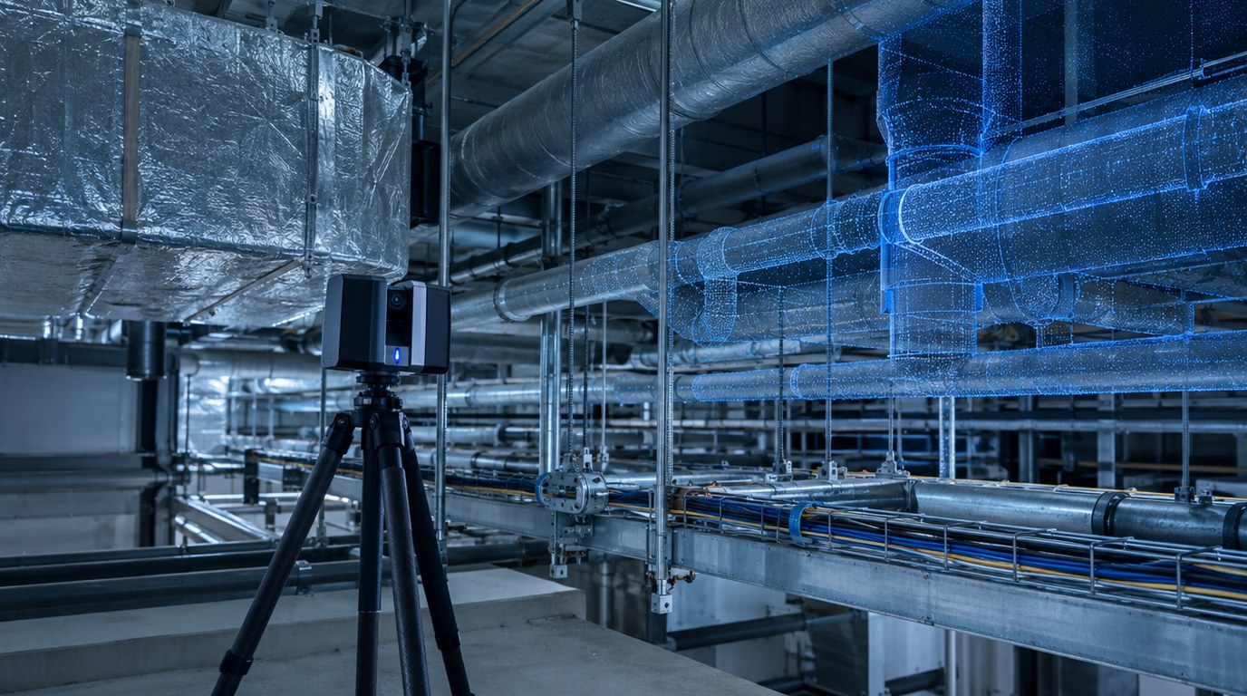
- Scan-to-BIM turns millions of measured points into a model that shows what is actually in the building.
- Retrofit conflicts are cheaper to find on a screen than in a ceiling, so scanning pays back during design.
- Define accuracy and level of development in the scope, because they control price more than any other choice.
- Scanners see surfaces only, so hidden pipes, conduits and slabs need separate investigation.
- The same model supports clash detection, prefabrication, commissioning and later facility management.
- Agency-reviewed projects such as schools and hospitals benefit from clean, verified existing conditions drawings.
- What Is Scan-to-BIM?
- How the Workflow Operates
- Capture Methods and Model Types
- Standards, Codes and Regulatory Context
- Applications by Building Type
- Process and Deliverables
- Special Cases and Hidden Conditions
- How to Specify and What Drives Cost
- Best Practices, Mistakes and Quality Control
- Where Budlong Delivers This
- Related Reading
- Frequently Asked Questions
Anyone who has opened a ceiling in an older building knows the surprise: a duct that is not on the drawings, a pipe that turns where it should not, a beam exactly where the new unit was meant to go. On retrofit projects those surprises become change orders and delays. Scan-to-BIM is the practice of replacing assumptions with measurements before design starts, and it has become a standard step for serious renovation work.
This guide explains how scan-to-BIM and as-built documentation work for mechanical, electrical and plumbing upgrades, written for owners, architects, developers and facility managers. Our MEP drafting services and MEP engineering services teams use existing conditions models to support everything from small tenant work to central plant replacements, and our leadership team has guided that approach across decades of renovation experience.
1. What Is Scan-to-BIM?
Scan-to-BIM begins with reality capture. A laser scanner or a similar device records the geometry of a building as a point cloud, a dataset of millions of measured points, each with a position in three dimensional space. A modeler then builds intelligent objects, such as walls, ducts, pipes, cable tray and equipment, directly over the cloud in BIM software. The outcome is a digital model that matches field conditions within a defined tolerance.
As-Built Versus Existing Conditions
The terms overlap but are not identical. As-built or record documents show what a contractor actually installed in a new project. Existing conditions documentation describes a building as it stands before a renovation, regardless of who built it or when. Scan-to-BIM is most often used for existing conditions, and it produces the starting point from which new as-built records will later be updated.
Why It Matters for MEP
MEP systems are dense, three dimensional and hidden. They share limited ceiling and shaft space with structure and architecture. A retrofit needs to know not only where equipment sits, but how much room remains around it for new routes. That is exactly what a good point cloud reveals.
Also Read: MEP BIM Coordination and Clash Detection
2. How the Workflow Operates
Every scan-to-BIM project follows the same arc, from planning through delivery.
- Scope and accuracy. The team agrees on the areas to scan, the elements to model and the tolerance required.
- Scan planning. Stations are positioned to minimize shadows behind equipment and to overlap for registration.
- Field capture. The scanner records each setup, often with panoramic photography for color and context.
- Registration. Software stitches setups into one coordinated point cloud and reports residual error.
- Modeling. Modelers trace the cloud to create objects with correct sizes, elevations and system types.
- Quality control. Deviation analysis compares the model with the cloud and flags areas outside tolerance.
- Delivery. The model, the cloud and supporting documents go to the design team.
From Cloud to Intelligent Model
A point cloud is a measurement, not a design tool. It cannot tell a supply duct from a return, or a gas line from a water line. The modeler adds that intelligence using system labels, equipment tags and field notes, which is why close collaboration with engineers makes the model more useful than a purely geometric trace.
3. Capture Methods and Model Types
No single capture method suits every building. The right tool depends on size, accessibility, required detail and budget.
Capture Technologies
- Terrestrial laser scanning: tripod-mounted scanners that deliver high accuracy and dense data, ideal for mechanical rooms and complex ceilings.
- Handheld or mobile SLAM scanning: faster for large floor areas, with lower accuracy than a tripod scanner.
- Photogrammetry: models built from overlapping photographs, useful for roofs and exteriors captured by drone.
- Total station and manual measurement: still valid for small areas and for verifying control points.
- Ground penetrating radar and electromagnetic locators: detect buried or embedded elements that scanners cannot see.
| Method | Best for | Speed | Typical limitation |
|---|---|---|---|
| Terrestrial scanner | Plant rooms, ceilings, structure | Moderate | Needs many setups in congested spaces |
| Mobile SLAM | Large open floors and corridors | Fast | Lower precision and more noise |
| Drone photogrammetry | Roofs, equipment yards, facades | Fast outdoors | Weather and airspace constraints |
| Radar and locators | Slabs and underground utilities | Slow and selective | Interpretation needs experience |
Model Types and Level of Detail
Two concepts keep expectations aligned. Level of development describes how much information and geometric detail model elements carry. Level of accuracy describes how closely the model matches the measured cloud. Industry groups publish specifications for both, and a project should cite them by name in the scope. A model for early feasibility can be loose, while one used to prefabricate pipe spools needs tight accuracy and fully modeled routes.
4. Standards, Codes and Regulatory Context
Scan-to-BIM is a method rather than a code requirement, yet several rule sets shape how existing conditions are documented and used.
Energy and Performance Standards
The ASHRAE library includes standards on energy efficiency in existing buildings and on commercial building energy audits. A model of existing systems makes audits more precise, which is why our ASHRAE Level 2 energy audit guide pairs well with this topic. In California, Title 24 Part 6 applies to alterations as well as new buildings, and the California Energy Commission publishes the current compliance material. The state’s 2025 Title 24 took effect on 1 January 2026.
Agency Review for Public Projects
Schools are reviewed by the Division of the State Architect, and hospitals by the Department of Health Care Access and Information. Both expect clear drawings of existing conditions where alterations touch life safety systems. See the Department of General Services and the HCAI sites for current procedures, and our DSA process guide for a plain-language summary.
Hazardous Materials and Worker Safety
Older buildings may contain asbestos, lead paint or other hazards. The U.S. Environmental Protection Agency and OSHA set the framework for surveys and protective work, and survey results should be known before ceilings are opened for scanning or investigation.
Data and Interoperability
The National Institute of Standards and Technology has long supported research on building information exchange, and open formats such as E57 and LAS for point clouds and IFC for models keep data usable across software. Specify them in the contract.
5. Applications by Building Type
Civic and Historic Buildings
Older city halls and civic structures have layered additions, unusual shafts and decorative ceilings that hide systems. Our portfolio includes work on Los Angeles City Hall and Pasadena City Hall. Scan data is particularly useful where destructive investigation is limited by preservation concerns. Learn more on our institutional page.
Schools and Campus Modernization
Modernization work happens in occupied campuses with tight summer windows. A scan taken during a break lets designers finish drawings before the next one. The LAUSD Jordan High School modernization is one example in our portfolio of how existing systems are upgraded within limited time.
Central Plants and Industrial Facilities
Plant rooms are among the most congested spaces in any building. Replacing chillers, boilers or generators requires exact rigging paths, clearances and pipe tie-in points. Our work on the central utility plant at LAX illustrates the scale of coordination involved. See also our industrial and laboratories practice.
Apartments and Mixed-Use Buildings
Multi-family renovations typically repeat unit types, so one well-scanned floor can guide many. Risers, shafts and corridor ceilings still need verification. Our multi-family page describes how we plan upgrades to shared systems.
Starting a Renovation or System Replacement?
Ask us how an existing conditions model can protect your schedule and budget before design begins.
Plan Your Retrofit with Budlong
Also Read: Early MEP Coordination Reduces Rework in Construction
6. Process and Deliverables
The most successful retrofit teams treat existing conditions as the first design deliverable instead of an afterthought. The model is created for a purpose, so define the questions it must answer: Can the new air handler be rigged through the corridor? Is there space for a larger riser? Which panels have spare capacity?
What the Model Should Include
- Major ductwork, piping and conduit with sizes, elevations and system names.
- Equipment with nameplate data, such as capacity, voltage and model number where available.
- Electrical panels, transformers, switchgear and their clearances.
- Plumbing risers, fixtures and key valves.
- Structural and architectural elements that constrain MEP routing.
Typical Deliverables
| Deliverable | Description | Downstream use |
|---|---|---|
| Registered point cloud | Unified scan data in an open format | Verification and future capture |
| Existing conditions BIM | Discipline models built to the agreed detail level | Design and clash detection |
| Plans, sections and schedules | 2D sheets generated from the model | Permit set and bidding |
| Deviation and QA report | Comparison of model with cloud | Confidence in accuracy |
| Unverified conditions list | Concealed items needing field confirmation | Risk planning and allowances |
When new design starts, the model becomes the host for coordination, as described in advancements in BIM for MEP coordination. If you are unsure how drafting differs from engineering on such a project, read MEP drafting services versus design services.
7. Special Cases and Hidden Conditions
What a Scanner Cannot See
A laser records the first surface it hits. It cannot see inside a wall, above a hard ceiling, within a slab or behind insulation. Plan for investigation: remove sample ceiling tiles, open access panels, use borescopes, and apply radar or electromagnetic locating where slabs and underground lines are involved.
Underground and Exterior Utilities
Buried lines are often documented poorly. Potholing and utility locating establish depth and material, and the results should be recorded with a stated confidence level so designers know which lines are verified and which are assumed.
Occupied and Operating Facilities
Hospitals, labs and data rooms cannot be shut down. Scans there must follow infection control and security rules, and scheduling must protect operations. Our health facilities team routinely works within those constraints.
Electrification and Capacity Upgrades
Replacing gas equipment with electric alternatives adds load to panels and service entrances, and often needs new conduit paths through crowded rooms. The existing model helps test those paths quickly. For context on the market shift, read our article on the impact of electrification on MEP engineering and the guidance on commercial building MEP upgrades that improve ROI.
Label every modeled element with a confidence level: scanned and visible, inferred from partial evidence, or assumed from drawings. Designers then know where a field verification is worth the cost.
Prefabrication and Digital Twins
Accurate models allow shops to fabricate pipe and duct sections off site, an approach discussed in modular and prefabricated MEP systems. The same data can feed operations platforms, which our article on integrating digital twin technology covers in depth.
8. How to Specify and What Drives Cost
A good scope tells the scanning provider exactly what to deliver. Name the areas, the disciplines, the target level of development, the accuracy level, the file formats, the coordinate system and the delivery date. Add a requirement for a written list of areas that could not be captured.
Cost Drivers
- Area and density: a congested plant room takes far more setups and modeling hours than an open office.
- Level of development: modeling every hanger and fitting is much more work than modeling major runs.
- Accuracy: tighter tolerance means more scan positions and more verification.
- Access and schedule: after-hours work, escorts and limited windows add time.
- Disciplines: adding structure and architecture to MEP increases the modeling scope.
- Investigation: opening ceilings, potholing and radar are separate line items.
| Project goal | Suggested detail | Why |
|---|---|---|
| Feasibility or space planning | Low detail, major equipment and shafts | Decisions need approximate sizes only |
| Design coordination and permit set | Moderate detail with accurate routes and clearances | New systems must fit existing ones |
| Prefabrication or tight plant replacement | High detail and high accuracy | Fit in the field depends on exact dimensions |
| Facility management baseline | Equipment-focused with asset data | Operations need tags and capacities |
Scanning is a small portion of design cost and can reduce construction risk more than almost any other early investment. For help placing it in a full budget, see how to estimate MEP engineering costs and the cost-oriented view in leveraging 5D BIM for MEP project management.
Also Read: Commissioning vs Retro-Commissioning
9. Best Practices, Mistakes and Quality Control
Best Practices
- Establish survey control points that tie scans to the building grid and to site coordinates.
- Scan and model each discipline with consistent naming, so the data can be filtered by system.
- Walk the building with the modeler and engineer before scanning to flag priority areas.
- Verify a sample of dimensions with a tape or total station and record the variance.
- Keep the point cloud with the model, so questions can be answered from the source data.
- Bring the commissioning agent into the process, since equipment data from the model helps testing.
Common Mistakes
- Scanning without a clear purpose and receiving a model that is either too rough or needlessly detailed.
- Assuming the scan shows concealed pipe, conduit and cable.
- Skipping a quality review, which lets modeling errors travel into the design.
- Failing to schedule access to locked rooms, roofs and shafts.
- Letting the model go stale after the first renovation phase.
Keeping Records Current
A scan is a snapshot. After construction, update the model with what the contractor actually installed, including field changes, so that the next project begins with an accurate record. Mechanical and plumbing designers should pay attention to piping that changes during construction, and a mechanical engineering and plumbing engineering review of the redlines keeps records honest. Electrical teams should update panel schedules and one-line diagrams in the same pass through electrical engineering services.
- Scan-to-BIM records visible conditions precisely, and a model built from it reveals conflicts before construction begins.
- State the purpose, detail level and accuracy in writing, and match them to the decision at hand.
- Investigate hidden systems separately and label confidence on every element.
- Use open formats and keep both the point cloud and the model.
- Update the model at closeout so that future projects begin with a verified baseline.
10. Where Budlong Delivers This
Budlong works from Glendale, downtown Los Angeles, Camarillo and Fremont, and supports projects in Los Angeles, Ventura, Orange, San Bernardino, Riverside and Santa Barbara counties, as well as across the Bay Area. Retrofit teams benefit from engineers who know the buildings and jurisdictions firsthand.
11. Related Reading
12. Frequently Asked Questions
What is scan-to-BIM?
Scan-to-BIM is the process of capturing an existing building with laser scanners or similar tools, producing a dense point cloud, and then modeling the visible architecture, structure and MEP systems in building information modeling software. The resulting model reflects field conditions rather than old drawings.
Why are existing drawings unreliable for retrofit design?
Drawings record design intent at one moment, and decades of tenant work, repairs and substitutions are rarely documented. Equipment gets relocated, piping is rerouted around obstructions and ceilings change. A retrofit that relies on the original drawings often meets conflicts that were invisible at design time.
How accurate is a laser scan?
Modern terrestrial scanners measure individual points to within a few millimeters. The accuracy of the final model depends on scan planning, registration quality, the modeling tolerance chosen and how well hidden elements can be verified, so the project should state a required accuracy level in the scope.
Can a scan show pipes and conduits hidden inside walls or slabs?
Not by itself. Laser scanning records visible surfaces only. Concealed elements require selective demolition, ceiling and access panel removal, borescope inspection, ground penetrating radar for slabs or electromagnetic locating, and these findings are then added to the model with a clear note of confidence.
What level of detail should the model have?
Match the level of development to the decision the model supports. Space planning needs little detail, while coordination of new ductwork, piping and conduit usually needs accurate sizes, routes and clearances. Modeling every fitting and hanger costs more and is justified only when the design depends on it.
How long does a scan-to-BIM project take?
Field scanning of a typical commercial floor often takes a day or less, while registration and modeling take longer and depend on floor area, density of systems and the target detail. Schedule the work early because design cannot proceed on firm ground until the model is verified.
Does the building have to be vacant during scanning?
No. Scanning is routinely done in occupied buildings, often after hours. Occupants and furniture can block views and create gaps, so access to mechanical rooms, ceilings and shafts should be arranged in advance and any sensitive areas identified before scanning begins.
How does an as-built model help with permits and agency review?
An accurate existing conditions model supports clear plans that reviewers can compare with the building. For schools and hospitals, which are reviewed by state agencies, correct documentation of existing systems reduces comments and speeds approval of alterations.
Who owns the point cloud and model after the project?
Ownership and permitted use should be stated in the contract. Owners generally want both the raw point cloud and the model delivered in open formats, since these become a baseline for future renovations, facility management and digital twin initiatives.