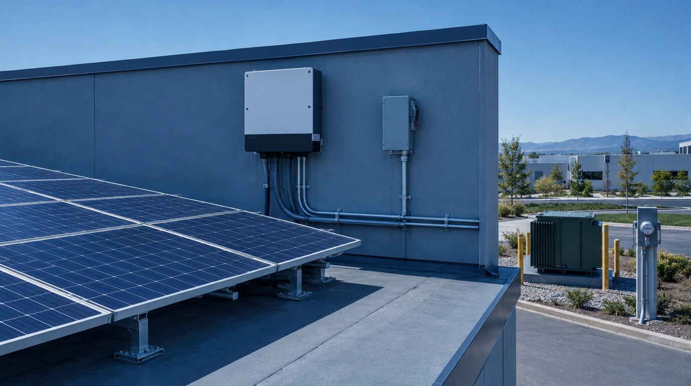
- IEEE 1547 defines how distributed energy resources must behave when connected to the grid.
- UL 1741 SB listing is the equipment-level proof that an inverter has been tested to those behaviors.
- California utilities apply a staged review, with initial screens, supplemental review and studies where needed.
- The National Electrical Code governs how the system is connected inside the building, including busbar limits and rapid shutdown.
- Protection settings, communications and witness testing are where many projects lose time.
- Early utility contact and an experienced PV design team keep the schedule predictable.
- What PV Interconnection Means
- How Grid Connection Works
- Connection Types and Smart Inverter Functions
- Standards and Rules That Apply
- Applications by Building Type
- Design Process and Deliverables
- Storage, Microgrids and Other Special Cases
- Specifying the Work and Cost Drivers
- Best Practices and Common Mistakes
- Where Budlong Delivers This
- Related Reading
- Frequently Asked Questions
A solar array that sits on a roof is only half a project. The other half is the legal and technical process of tying it to the utility’s wires, and that half is where schedules slip. Interconnection is a negotiation between your electrical design and the rules of a distribution network that was built to deliver power one way. Getting it right calls for electrical engineering that understands both sides of the meter.
This article walks through how interconnection works, what IEEE 1547 requires, how California utilities process applications and what developers and owners should prepare. It draws on a firm history that began in 1958, and on current work in solar PV design for commercial and institutional clients. To learn more about the people behind it, visit our company story.
1. What PV Interconnection Means
The Point Where Your System Meets the Grid
PV interconnection is the set of physical connections, protective devices, settings, agreements and approvals that allow a solar generating system to operate in parallel with the utility. It spans equipment on your side, such as inverters, combiners, disconnects and switchgear, and equipment on the utility side, such as transformers, line protection and metering.
Why the Rules Exist
Utilities must protect line workers, protect other customers and keep voltage and frequency within limits. A generator that keeps energizing a dead line during an outage is a hazard. A cluster of systems that all trip at once during a voltage dip can destabilize a circuit. Interconnection rules prevent both outcomes.
What IEEE 1547 Adds
IEEE 1547 is the national standard for the interconnection and interoperability of distributed energy resources. It describes how a resource must behave at the point of interconnection: how it regulates voltage, how it responds to abnormal voltage and frequency, how it detects an unintended island and how it communicates. The IEEE Standards Association maintains the standard and its companion test procedures.
2. How Grid Connection Works
The Physical Path of Power
Direct current from the array flows to one or more inverters, which convert it to alternating current in step with the grid. The inverter output passes through overcurrent protection and a disconnecting means, joins the building’s electrical system or a dedicated service, and connects to the utility through a point of common coupling. Small systems commonly connect behind the customer’s meter. Larger systems may use a dedicated transformer and a separate utility meter.
Anti-Islanding and Ride-Through
Under IEEE 1547, a resource that finds itself powering an isolated section of the grid must stop energizing it within a short, defined time. Equally, the resource must stay connected through brief voltage and frequency disturbances, rather than all tripping at once. These two ideas, trip when you must and ride through when you can, are the core of modern inverter behavior.
Voltage Support
Solar output can raise voltage on a lightly loaded feeder. Smart inverters counter this by absorbing or injecting reactive power, or by reducing active power when voltage climbs. The utility specifies which functions to enable and what curve settings to use.
The Review Pathway
In California, investor-owned utilities process applications under a tariff known as Rule 21. Municipal utilities, including those serving parts of Los Angeles, publish their own rules. Both use a staged approach that screens each application against circuit conditions, then escalates to supplemental review or a study if a screen is not met.
Also Read: The Complete Guide to Photovoltaic System Design Engineering
3. Connection Types and Smart Inverter Functions
Load-Side and Supply-Side Connections
Inside a building, solar can connect on the load side of the service disconnect, at a panelboard or switchboard, or on the supply side, ahead of the main. Each has trade-offs. A load-side connection is simple but is limited by the busbar rating rules in the National Electrical Code. A supply-side connection avoids those limits but needs listed equipment and careful coordination with the utility’s service.
| Connection | Typical use | Main advantage | Main constraint |
|---|---|---|---|
| Load side, existing panel | Small to mid-size rooftop | Lowest hardware cost | Busbar and breaker limits |
| Supply side, ahead of main | Older switchboards with little busbar margin | Avoids busbar limits | Needs listed tap equipment and utility coordination |
| Dedicated service and transformer | Larger systems, ground-mount and carports | Clear separation and metering | Higher equipment and permitting effort |
| Medium-voltage tie | Utility-scale or campus systems | Efficient at high capacity | Relay protection, studies and possible transfer trip |
Smart Inverter Functions
IEEE 1547 groups the grid-support behaviors into functions that the utility can enable. The table summarizes the ones that matter most in design discussions.
| Function | What it does | Why the utility cares |
|---|---|---|
| Volt-var | Adjusts reactive power with local voltage | Limits voltage rise on feeders |
| Volt-watt | Reduces active power at high voltage | Prevents overvoltage at high solar output |
| Frequency-watt | Reduces output when frequency is high | Supports frequency stability |
| Voltage ride-through | Stays connected through short dips and swells | Avoids mass tripping |
| Frequency ride-through | Stays connected through frequency excursions | Preserves generation during disturbances |
| Remote communication | Accepts settings and reports status | Allows utility to manage settings |
4. Standards and Rules That Apply
IEEE 1547 and Its Test Procedures
IEEE 1547 sets requirements for the interconnection. A companion document, IEEE 1547.1, defines how conformance is tested. Manufacturers use it to prove that their equipment meets the standard.
UL 1741 and Equipment Listing
Inverters sold in the United States are evaluated under UL 1741, with a supplement known as SB covering the functions in the current IEEE 1547 edition. UL Solutions publishes information about listings. A project’s inverters should carry the listing that the utility expects at the time of application.
The National Electrical Code
Article 690 covers photovoltaic systems, including rapid shutdown, conductor sizing and disconnects. Article 705 covers interconnected power sources, including the rules for load-side and supply-side connections. California adopts the code through the California Electrical Code, so confirm the adopted edition before designing. The National Fire Protection Association publishes the model code. For storage, NFPA 855 sets installation requirements for energy storage systems.
California Building and Energy Rules
The California Energy Commission administers the energy standards that, for many new nonresidential buildings, call for on-site solar. See its building energy efficiency standards page for the adopted edition. Our overview of Title 24 explains how those rules reach the design.
Utility Tariffs and Handbooks
Each utility publishes application forms, technical requirements and metering rules. These documents define screen criteria, required studies, communications protocols and witness test expectations. Read them before design is final.
5. Applications by Building Type
Commercial Offices and Retail
Large roofs, daytime loads and predictable operating hours make commercial buildings strong candidates. Interconnection is typically behind the meter, so the main issues are busbar capacity, roof structure and export limits. Our article on commercial solar PV design covers the business case in more detail.
Warehouses and Industrial Sites
Broad roofs and heavy loads make industrial buildings attractive, but older switchgear may lack room for a new connection. A supply-side tap or a new service section is common in these cases. Process loads also make power quality studies worth doing.
Schools and Public Buildings
Parking canopies and roof arrays on schools are common. Approval by the state architect applies to many school projects, so interconnection design and structural review should run together. Our DSA process guide explains that review path.
Hospitals and Mission-Critical Facilities
These sites have emergency power systems that must not be compromised. Solar must be arranged so that the transfer from utility to generator is unaffected and the inverters stay off the emergency branch unless specifically designed for it. Existing generator work, such as the LACMTA emergency generator replacement, shows how carefully backup systems must be handled.
Transit and Fleet Charging
Charging depots combine large loads with the opportunity for solar and storage. Projects such as the LAX bus charging station show the scale of electrical service these facilities need, and the same planning applies when solar is added.
Planning a Solar Project?
Our electrical engineers prepare the single-line diagrams, protection studies and utility applications that move a project from concept to permission to operate.
6. Design Process and Deliverables
Step 1: Feasibility and Circuit Review
Start with a feasibility study that tests roof or site capacity, structural constraints, shading, loads and the likely interconnection route. Request any pre-application information the utility offers. Our resource on PV feasibility and design describes this stage.
Step 2: Load and Service Evaluation
Review existing service size, busbar ratings and spare capacity. A current electrical load calculation shows whether the building can accept the system as proposed.
Step 3: Single-Line Diagram and Protection Design
The single-line diagram is the document the utility reads first. It shows equipment ratings, the point of interconnection, protective devices, grounding and metering. For larger systems, a relay protection design lists the device functions, settings and coordination with utility protection.
Typical Protection Functions
- Undervoltage and overvoltage trips
- Underfrequency and overfrequency trips
- Synchronism check before closing
- Overcurrent and ground fault protection
- Reverse power or export limiting where required
Step 4: Application Package
A complete package normally includes the application form, site plan, single-line diagram, equipment data sheets, listing evidence, protection settings and proof of ownership. Incomplete packages are the most common cause of avoidable delay.
Step 5: Study Support and Agreement
If the utility requires a study, the design team responds to technical questions, evaluates upgrade options and helps the owner review the cost allocation. The final interconnection agreement records responsibilities and operating limits.
Step 6: Construction, Inspection and Commissioning
After installation, the local building authority inspects. The utility then reviews final documents, may witness tests and issues permission to operate. Commissioning verifies inverter settings, protection trips and communications. See our guidance on commissioning for how this fits a wider project.
Also Read: Rooftop Solar PV Design Services: Maximizing Energy Output
7. Storage, Microgrids and Other Special Cases
Adding Battery Storage
Storage changes the picture. It can charge from the grid or from solar, and it can export or hold output. The utility reviews the intended operating mode, and the fire authority reviews the installation under the storage standards. The National Renewable Energy Laboratory publishes research on solar and storage integration that can inform early planning.
Backup Power and Islanding
A grid-tied inverter shuts down during an outage. To keep parts of a building running, the design needs a transfer arrangement that isolates the building from the grid, plus a source that can form a voltage reference. This is a different design problem from simple export and it changes protection, grounding and controls.
Microgrids and Campuses
Campuses with several buildings can use a shared medium-voltage tie, central controllers and coordinated protection. These projects have a longer approval path and need an agreement that describes operating modes. The U.S. Department of Energy offers background material on microgrids and distributed energy.
Existing Buildings With Older Equipment
Older panels may lack spare space, may have damaged busbars or may have no arc flash labeling. A compliant solar tie-in may trigger upgrades. Plan for an arc flash analysis, since a new source changes available fault current.
Large Ground-Mount Projects
Utility-scale projects add collector systems, substations and transmission-level studies. The design resources on utility-scale solar engineering cover the added considerations.
Also Read: Commercial Solar PV Design: Transform Your Business Energy
8. Specifying the Work and Cost Drivers
What to Ask For
When engaging a design team, ask for experience with your utility, evidence of completed applications and a clear description of who handles the utility communication. The guidance on finding a solar PV design consultant offers a useful checklist.
Specification Points
- Require inverters with the listing and functions the utility expects.
- State who provides protection settings and who commissions them.
- Describe metering, communications and monitoring needs.
- Require arc flash labels and updated one-line diagrams at turnover.
What Drives Cost
| Cost driver | Effect | Mitigation |
|---|---|---|
| Utility upgrades | Transformer, line or protection changes charged to the project | Request early screening and test alternate sites |
| Switchgear modification | New sections or replacements for older gear | Use supply-side tie or relocate the point of connection |
| Protection and relaying | Added relays, communications and testing | Size the system to stay below study triggers where practical |
| Storage fire review | Added separation, ventilation and detection | Coordinate siting with the fire authority early |
| Schedule delay | Lost generation and extended carrying cost | Submit complete packages and respond to comments quickly |
9. Best Practices and Common Mistakes
Practices That Work
- Check circuit hosting information before choosing the site.
- Match the number and size of inverters to the screens, not only to the roof.
- Coordinate the single-line diagram with the real panel schedules.
- Confirm the communications protocol and test it before the witness visit.
- Keep one owner contact for all utility correspondence.
Mistakes to Avoid
- Ordering inverters before confirming the utility’s accepted list.
- Assuming the existing busbar can take the new breaker.
- Submitting a single-line diagram that does not match the field.
- Overlooking emergency system impacts in hospitals and critical buildings.
- Energizing before receiving written permission to operate.
Testing and Maintenance
Verification tests confirm trip points, ride-through behavior and communications. Periodic maintenance should include thermal scans, torque checks on connections and review of inverter event logs. Research on field performance is published by the Lawrence Berkeley National Laboratory.
Keep a copy of the approved settings file with the project record. If an inverter is replaced years later, the new unit must be configured to the same utility-approved values.
- IEEE 1547 defines grid behavior, and UL 1741 SB listing proves the equipment can deliver it.
- Utility review is staged, so project size and location affect the path.
- The National Electrical Code limits how and where solar can tie into a building.
- Protection, communications and witness testing deserve as much attention as module layout.
- Storage and backup power add review steps and design changes.
10. Where Budlong Delivers This
Budlong electrical teams work from Glendale, downtown Los Angeles, Camarillo and Fremont, supporting clients in Los Angeles, Ventura, Orange, San Bernardino, Riverside and Santa Barbara counties. Local experience with nearby utilities and building departments helps applications move.
11. Related Reading
12. Frequently Asked Questions
What is IEEE 1547?
IEEE 1547 is the standard that sets technical requirements for connecting distributed energy resources, including solar inverters and storage, to the electric grid. It covers voltage regulation, ride-through, islanding response, power quality and interoperability.
What does UL 1741 SB certify?
It certifies that an inverter or other grid-support equipment has been tested to perform the functions expected under IEEE 1547. Utilities in California generally expect certified equipment to be listed for an interconnection application.
How long does PV interconnection take?
Timelines vary widely. Small systems that pass initial screens can move quickly, while larger systems that need supplemental review, studies or utility upgrades can take many months. Early engagement with the utility shortens the path.
What is a smart inverter?
A smart inverter is a grid-support inverter that can adjust its output in response to voltage and frequency, ride through disturbances, and accept remote settings. These functions help the grid absorb more solar.
Do I need a study for every solar project?
No. Many projects pass the utility’s initial review screens with no study. Larger systems, or systems on circuits with limited capacity, may require a supplemental review or a full study.
What is the 120 percent rule?
For load-side connections to a busbar, the National Electrical Code limits the sum of the main breaker and the solar breaker to a percentage of the busbar rating. Supply-side connections and power control systems are common ways to work within that limit.
Can a PV system keep running during a utility outage?
Not by itself. Grid-tied inverters must stop energizing the grid during an outage. To operate through an outage, a project needs an islanding-capable design, such as energy storage and a transfer arrangement that isolates the building from the grid.
Does adding battery storage change the interconnection?
Yes. Storage is treated as a distributed energy resource and is reviewed for its export behavior, its charging source and its fire and safety requirements, in addition to the normal solar review.
What happens after the utility approves the application?
The owner signs an interconnection agreement, completes construction and inspection by the local building authority, and then receives written permission to operate from the utility before energizing the system.